Working With Figures (Select Tool)Setting Figure Properties |
Last updated on 11/12/2010 |
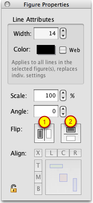
To set properties for one or more figures, you will need to make sure that the Properties palette is displayed (Window > Properties), and that you have one or more figures selected on the Stage (their nodes will be red to indicate they are selected). This will make sure the Figure Properties are shown in the Properties palette.
Width
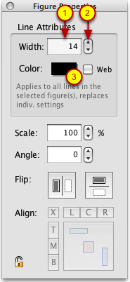
To change the width (thickness) of the line segments of a figure, you can do one of the following:
(1) Click in the Width field and type in a new value and hit the Enter or Return key, or
(2) Use the spinner control to the right of the field to raise or lower the width on the fly. If you just click on one of the arrows, it will increase or decrease the value by one. If you click on an arrow and hold down, it will adjust the scale slowly at first, but then accelerate after a few seconds to jump in larger increments. Release the mouse button to stop the adjustment.
NOTE: The value for Width can be any number (integer) from 1 to 256. Circle segments have an additional restriction on the maximum value - the width of a circle cannot be larger than its length. or more information on circle segment width, see Working With Circle Segments.
PIVOT COMPATIBILITY NOTE: In Pivot, you can set the thickness of a segment to 0 to make it disappear. To do the same thing in Stykz, just click the Hidden checkbox in the Properties Palette for the selected segment(s).
Color
To change the color of the line segments of a figure, simply click on the color swatch (3) and select a color. If you want to restrict the color selection to only Web Safe colors, click the Web checkbox. For more on selecting colors and the purpose of the Web checkbox, see Selecting Colors.
IMPORTANT: Changing the Width or Color of a figure will affect ALL of the segments of the figure. That is, if you had some segments with a width of 7 and others with a width of 12 and you entered 14 for a width and hit the Enter key, every segment of the figure would be given a width of 14. (If you forget this and accidentally change all of the segments to a value you didn't intend, you can always use Edit > Undo to put it back the way it was.)
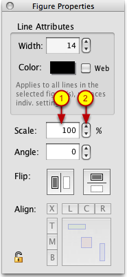
To change the scale of a figure, you can then do one of the following:
(1) Click in the Scale field and type in a new value and hit the Enter or Return key, or
(2) Use the spinner control to the right of the field to raise or lower the scale on the fly. If you just click on one of the arrows, it will increase or decrease the value by one. If you click on an arrow and hold down, it will adjust the scale slowly at first, but then accelerate after a few seconds to jump in larger increments. Release the mouse button to stop the scaling.
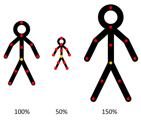
NOTE: Scaling affects all selected figures, and is restricted to a range of 1% to 500%. Scaling affects all parts of a figure, so the width of lines (thickness) will scale as well. Example:
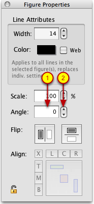
To rotate of a figure, you can then do one of the following:
(1) Click in the Angle field and type in a new value and hit the Enter or Return key, or
(2) Use the spinner control to the right of the field to raise or lower the angle on the fly. If you just click on one of the arrows, it will increase or decrease the value by one. If you click on an arrow and hold down, it will adjust the angle slowly at first, but then accelerate after a few seconds to jump in larger increments. Release the mouse button to stop the rotation.
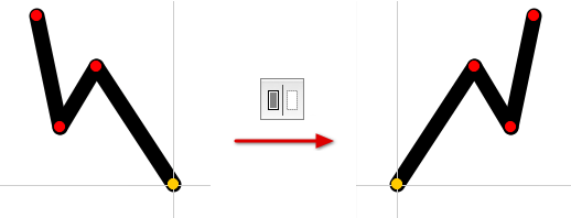
You can flip one or more selected figures by clicking the Flip Horizontal button (1) or the Flip Vertical button (2). The figure(s) are flipped using the drag node as the "flipping point", for example:
Aligning two or more selected figures is a two-step process:
(1) Select the alignment method you want from either or both of the TMB or LCR button sets;
(2) Click the big Align button.
This is covered in more detail below:
Choosing the Alignment Method
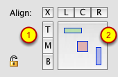
The "T", "M", and "B" buttons are for vertical alignment, and represent Top, Middle, and Bottom options. The "L", "C", and "R" buttons are for horizontal alignment, and represent "Left", "Center", and "Right". Clicking any of the T/M/B or L/C/R buttons will cause them to be highlighted and the graphical representation of alignment on the Align button will change to show you how the alignment choices you made will play out. Here's some examples:
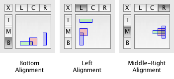
If you want to clear your alignment method choices, click the "X" button in the upper-left and any selections you made in the T/M/B or L/C/R button sets will be removed.
Aligning the Figures
Once you have the alignment method you want, click the big square Align button (the one with the colored rectangles on it) to cause the selected figures to be aligned. (If you make a mistake, you can always Edit > Undo and try again.)
IMPORTANT: Figures will be aligned to the first figure selected (either by being the first figure clicked on or the first figure touched/enclosed by a selection rectangle). For an example of how this works, take a look at this video tutorial on YouTube.
Locking Figures
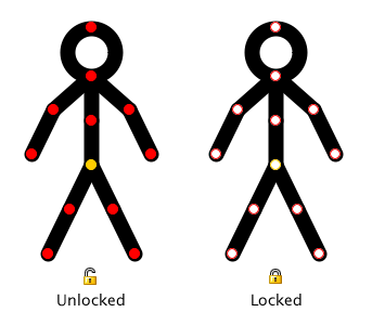
There are times when animating where you are trying to click on something and you click on something else by mistake, accidentally moving or changing a figure that you didn't want to touch. Although you can Undo actions like that, Stykz allows you to lock figures so that they cannot be moved or manipulated using the mouse. To do so, simply click the padlock icon on the Figure Properties palette. Locked figures have their nodes (both drag and pivot) change to white to indicate they are locked (although the border around the nodes will be red or blue to indicate if the figure is selected or not):
